Tuesday, November 3, 2020

Using a C# EXE to interact with AutoCAD

I'm updating this because I've found out that the method explained below has problems, and that you'd do better making a C# DLL to run inside AutoCAD, or use C# with ObjectDBX to run as an EXE which talks to AutoCAD.

The problem is that Microsoft changed the way .NET works, details here, which means that Documents.Open  can sometimes fail. The error code is HRESULT: 0x80010001 (RPC_E_CALL_REJECTED). It is to do with the fact that AutoCAD is still initializing when the call is made, so you need to add some sort of delay, or catch an exception, or maybe wait till it is visible. This is my solution, though I don't like having to do this:

            AcadDocument AcadDoc = null;

            int iNumTries = 0;
            const int ikMaxTries = 400;
            while (iNumTries < ikMaxTries)
            {
                bool bError = false ;
                try
                {
                    AcadDoc = AcadApp.Documents.Open(@"C:\DisegniSviluppati\04.DWG");
                    AcadDoc.Activate();
                }

                catch (Exception e1)
                {
                    Debug.WriteLine("Catch on try " + iNumTries.ToString() + ", exception: " + e1.Message + "\n");
                    bError = true;
                }

                if (!bError)
                {
                    break;
                }

                if (iNumTries == ikMaxTries)
                {
                    break;
                }

                iNumTries++;
            }

            if (iNumTries == ikMaxTries)
            {
                // Failure
                return;
            }

            // Now we will loop over all the entities in the drawing we have just saved and re-opened...
            var ModelSpace = AcadDoc.ModelSpace;
            int iNumEntities = ModelSpace.Count;

Essentially I stay in a loop trying to open the drawing until I don't get an exception. The source below will work generally, but be ready to strange and random exceptions, depending on the timing of your program.

Here's the old article:

Saturday, October 31, 2020

When cool beats useful, the NETGEAR N300 WNR2000v5 router

You'd think after all these years of studies on design for usability companies would have learned something. Netgear has not. Here is their NETGEAR N300 WNR2000v5 router.

The electronics work decently (I have to do a reset every two days or so), but why have they hidden the WPS button in plain site? If you do not do network setups as your job then you do it at most once a year. So the icons mean nothing. And WPS is meant to make things easy for ordinary users.

Where on earth is the WPS button which would allow me to connect simply and quickly to a wi-fi booster? I've already given you a clue by showing you only 1 of the 6 sides...there are other buttons hidden and unlabeled on the other sides of the device.

It is the triangle next to the padlock. And here you can see where "cool" beats useful. The designer wanted to be "cool" so the icon is tiny and non standard. The buttons, instead of being round are "coolly" triangular and look like LEDs. The icon is actually only 3mm wide, so anybody with vision problems is not going to be able to see it clearly.

The "cool" designer needs to go back to school and learn about usability. Oddly enough an earlier design (2017?) was much clearer:


The button is round, there is the icon (useful if you know what it means, and not the standard for WPS) but there is the acronym WPS in clear lettering underneath it.


Sunday, September 13, 2020

The Visualization of Points of View

I'm a fan of Edward Tufte and have all three of his books on Visualization of Data (see bottom of this page). It occurred to me that you could show the two "extreme" points of view of Covod-19 in a single info-graphic.

So there are those who say Covid-19 is a hoax or not really a problem, and there are those who say it is a catastrophe for humanity. I think the two points of view are summed up by this image:


The population of England and Wales is 57 million, and the number of deaths from Covid-19 this year is about 42,000 (so far). So the doubters say: "Deaths caused by Covid are less than 0.074% of the population.

You can hardly see the thin red line under the red text of the bar graph.

Personally I think that, yes, the number of people directly affected is very very tiny, but the effect on the nurses, doctors, actual patients, our healthcare system is huge, and we must respect that fact.

Anyway this info graphic came to my mind so I made it.

Here are the wonderful books of Edward Tufte, full of examples of good and bad info-graphics, a joy to see, read and understand. Anybody who thinks that Excel's graphing functions are all you need to know, should read at least one of these.


Sunday, March 29, 2020

Neural Networks on the Arduino Part 6: Putting it all together, training and testing your neural network


We are almost there! We can nearly put all the code together. All we need is some test data to call UpdateWeights with (for the training) and some test data (for the testing).

At this point it would be a good idea copy the source code into the Arduino IDE and follow this article while looking at the sources.

For one of the tests I'm going to use the same one as I used here in the Python implementation by Tariq Rashid. The neural network is presented with a spike in a graph and must return the position of that spike.

Here is how I create the test data:

// This creates a test input vector and the ideal output for that input
void CreatePositionTrainingSample (mtx_type* TrainInputVector,

                                   mtx_type* TrainTargetVector)
{
    // A check to stop silly errors as you meddle with the code...
    if (NUM_OUTPUTS != 2) {
        Serial.print ("Training sample error, I want 2 outputs!") ;
    }
 
    // Choose a place from 0 to (NUM_INPUTS-1)
    int iPos = random (0,NUM_INPUTS) ;  
   
    // Make a vector with a spike at the randomly chosen iPos
    for (int i = 0 ; i < NUM_INPUTS ; i++) {
        if (i == iPos) {
            TrainInputVector[i] = 1.0 ;      
        } else {
            TrainInputVector[i] = 0.0 ;
        }
    }
    // Now we have an input vector with a single non zero value

    // What is the expected output number?
    // We want one output to be at the "value of the position" so to speak
    double OutputValue1 = (double)iPos/double(NUM_INPUTS-1) ;

    // Just to have more than one output...
    // ...make other output to be at the "opposite of the value of the position"
    double OutputValue2 = 1.0 - OutputValue1 ;

    // This is the idea correct answer...
    TrainTargetVector[0] = OutputValue1 ;
    TrainTargetVector[1] = OutputValue2 ;
}


So if the function creates an input vector with a spike in the middle:

{0,0,1,0,0}  

I get an output value of 0.5.

And if the function creates an input vector with a spike at the end of the vector.

{0,0,0,0,1}  

I get an output vector 1.0.

And so on.


Actually, to keep things interesting, I have two outputs, the position of the spike and its mirror image, that is what OutputValue2 is in the above function.

Be careful with the use of random(). The second parameter is exclusive.

That position test is actually a simple problem for neural networks, a harder one is XOR. The XOR problem is what prompted the use of the hidden layer. The XOR problem cannot be solved with a single layer neural network. There's plenty on the internet about the XOR problem so I won't go into it here, but to make sure we've got things right in our two layer Arduino neural network we must test it with the XOR problem.

Basically if there are two inputs when both are active (=1) the output should be inactive (0). And if only one of the two inputs are active then the output should be active.

Looking at it another way, the neural network should detect if the two inputs are different. If they are both 0 or both 1 then the output should be 0.

Here's a table which illustrates that:


inputs       XOR    XNOR
0    0        0      1
0    1        1      0
1    0        1      0
1    1        0      1


I've added XNOR an output as well, just to make it interesting. XNOR is simply the opposite of XOR, as you can see in the above table.

Here's how I create a sample for the XOR training and testing:

void CreateXORTrainingSample (mtx_type* TrainInputVector, mtx_type* TrainTargetVector)
{
    // A check to stop silly errors as you meddle with the code...
    if (NUM_OUTPUTS != 2) {
        Serial.print ("Training sample error, I want 2 outputs!") ;
    }
    if (NUM_INPUTS != 2) {
        Serial.print ("Training sample error, I want 2 inputs!") ;
    }
    
    // Choose a row in the truth table...
    int iWhichRow = random (0,4) ;  // will give me a number from 0 to 3 inclusive

    if (iWhichRow == 0) {
        TrainInputVector[0] = 0 ;  // INPUT 1   
        TrainInputVector[1] = 0 ;  // INPUT 2
        TrainTargetVector[0] = 0 ; // XOR  
        TrainTargetVector[1] = 1 ; // XNOR  
       
    } else if (iWhichRow == 1) {
        TrainInputVector[0] = 1 ;     
        TrainInputVector[1] = 0 ;     
        TrainTargetVector[0] = 1 ;  
        TrainTargetVector[1] = 0 ;  

    } else if (iWhichRow == 2) {
        TrainInputVector[0] = 0 ;     
        TrainInputVector[1] = 1 ;     
        TrainTargetVector[0] = 1 ;  
        TrainTargetVector[1] = 0 ;  
   
    } else {
        TrainInputVector[0] = 1 ;     
        TrainInputVector[1] = 1 ;     
        TrainTargetVector[0] = 0 ;  
        TrainTargetVector[1] = 1 ;  
    }
}


Now, in the whole source code I've made it possible for you to use either of these tests by simply setting a define to 1:

// To decide the type of test one of these should be 1 and the other 0
#define XOR_TEST 0
#define POSITION_TEST 1


The number of inputs outputs and hidden nodes will change according to what sort of test you use.

Note also that in the same place in the code I set the  NUM_TRAINING_SAMPLES to depend on if we are doing XOR_TEST or POSITION_TEST. NUM_TRAINING_SAMPLES is much higher for the XOR test because XOR is a harder problem.

The top level of the program starts at void loop() near the end of the sources. First the network is trained, and then it is tested.

You need to run the serial monitor to see the output of the training and of the testing. Here is the output when POSITION_TEST is used:


TrainOnOneSample is called repeatedly (from inside RunMultipleTrain) in order to slowly modify the weights.

Inside TrainOnOneSample is the define QUERY_AS_YOU_UPDATE. If that is set to 1 then you will test the neural network after every single train and print the results. If it is set to 0 you will only see the final test results.

Now it is up to you to decide what...
  1. light inputs
  2. light outputs
  3. motors
  4. servos
  5. solenoids
  6. switches
  7. relays
  8. varistors
  9. transistors
  10. robots
  11. robot arms
  12. robot legs
  13. touch sensors
  14. pressure sensors
  15. meteorological sensors
  16. ...

...you want to use this program with!

Whatever you decide I think you'll probably need to increase the number of hidden nodes.


Neural Networks on the Arduino Part 5: How to update the weights

Previously I said that since we have to sets of weights to update (= two matrices to change) we may as well write a single function and call it twice.
 
So what are the inputs and outputs of our back propagation weight adjusting C like function? I'd suggest...
  1. iNumLocalInputNodes
  2. InputValues (a vector  iNumLocalInputNodes big)
  3. iNumLocalOutputNodes
  4. OutputValues (a vector iNumLocalOutputNodes big)
  5. ErrorValues (a vector iNumLocalOutputNodes big) 
  6. WeightMatrix (with iNumLocalInputNodes rows and iNumLocalOutputNodes columns)
I like to draw (pencil and paper away from the computer!) diagrams of functions I'm going to write, just to make sure I have them correct in my head. If I don't have them clear in my head I will have a snowflake's chance in hell of writing the function correctly.


Note that the inputs and outputs are not necessarily the inputs and outputs of the whole network. The above function will be called first for the hidden to output part and then again for the input to hidden part. That is the point of writing the function, so it can be used in more than one place.

Here is the code, note that I use the WeightMatrix as both an input and output.

// Change the weights matrix so that it produces less errors
void UpdateWeights (int iNumInputNodes,  mtx_type* InputValues, // a col vector
                    int iNumOutputNodes, mtx_type* OutputValues, // a row vector
                    mtx_type* ErrorValues, // same size as output values
                    mtx_type* WeightMatrix) // This is an input and output
{
    // This is just to keep sizes of matrices in mind
    int iNumRows = iNumInputNodes ;
    int iNumCols = iNumOutputNodes ;
   
    // The f "horizontal" row vector is formed from
    // alfa*(error*(output*(1-output)) in each column
    // Initialised from errors and outputs of this layer, and so has the same
    // size as the error vector and output vector
    mtx_type f[iNumOutputNodes] ;

    for (int col = 0 ; col < iNumOutputNodes ; col++) {
        // The outouts have been created using the sigmoid function.
        // The derivative of the sigmnoid is used to modify weights.
        // Fortunately, because we have the outputs values, the derivative
        // is easy to calculate...Look up derivative of sigmoid
        const double SigmoidDeriv = OutputValues[col]*(1.0-OutputValues[col]) ;
        f[col] = Alpha*ErrorValues[col]*SigmoidDeriv ;
    }

    // The "vertical" column vector is the inputs to the current layer

    // Now we can do the outer product to form a matrix from a
    // a column vector multiplied by a row vector...
    // to get a matrix of delta weights
    mtx_type ErrorDeltasMat [iNumRows*iNumCols] ;
    OuterProduct((mtx_type*)InputValues,
                  f,
                  iNumRows, 
                  iNumCols,
                  (mtx_type*)ErrorDeltasMat) ;

    // Now we have the deltas to add to the current matrix
    // We are simply doing OldWeight = OldWeight+DeltaWeight here
    for (int row = 0 ; row < iNumRows ; row++) {
        for (int col = 0 ; col < iNumCols ; col++) {
            int iIndex = (row*iNumCols)+col ;
            WeightMatrix[iIndex] = WeightMatrix[iIndex] +
                                   ErrorDeltasMat[iIndex] ;
        }
    }

}
In the above code Alpha is the learning rate, often between 0.1 and 0.2, and a constant defined elsewhere in the Arduino program.

The SigmoidDeriv is the derivative of the sigmoid function, and is calculated like this:

S' = S(1-S)

Now the outputs of our layers are the sigmoids of the inputs. So the derivative is simply (theoutputs*(1-theoutputs)) as shown in the code above. Simples!


Neural Networks on the Arduino Part 4: Calculation of hidden errors in a neural network


Of all the things I found hard to "believe" "understand" or "grok" was how the hidden errors are calculated in a neural network. If you've done matrix maths the equation seems far too simple to be true. Here I'll illustrate to you, and to myself, how it works.

The problem is that while it is clear what an error is at the output of a neural network, it is not immediately clear what an error is at the hidden layer output. Graphically:


It turns out that a good approach is to use the errors at the output to set the "errors" in the hidden layer.

(By the way you can't just copy the output errors into the hidden layer because there is no guarantee that the number of outputs is the same as the number of hidden nodes. Plus the fact that you'd be arbitrarily jumping over the HiddenToOutput matrix.)

So the idea is that the hidden layer errors are weighted averages of the errors at the output. We make the assumption that an error at the output has been caused by an "error" in the hidden layer. How much the error at the output has been caused by the error in the hidden depends on the weight connecting the two nodes (errors).


For example look at eH2 above, it contributed to errors at eO1 and eO2, and how much it contributed depended on the weights wa and wb. So eH2 will be a weighted average of eO1 and eO2. As explained in the book by Tariq Rashid, we do not need to use an actual weighted average, we can just use the weights directly.

In other words...

eH2 = wa*eO1 + wb*eO2

Luckily this can be nicely done with matrices, and the matrix of the weights for this back propagation of errors is easily created from the forward hidden to output matrix.

I'm about to demonstrate that, by the magic of matrices, the matrix which gives us the hidden "errors" from the output errors is simply the transpose of the forward hidden to output matrix! Lets look again at how the forward hidden to output matrix works:


I've arranged the weights closer to the output nodes so you can see the calculation better. Study and understand how o1 is calculated. Compare the drawing and the matrix versions in the above image.

So. That is how the forward calculation of the outputs work. How do we do the backward propagation of the errors using matrix multiplication? Here's another, this time illustrating the backward propagation of errors from the output to the hidden layer:


  • I've drawn the errors flowing rightwards, from eo1 to eh1 etc. This is so you can easily relate the diagram to the matrix multiplication.
  • The o in eo2 (for example) stands for output
  • The h in eh3 (for example) stands for hidden
  • I've drawn the weights which modify the output errors to form the hidden "errors" close to the hidden error nodes
  • I've drawn the hidden error calculations at top right of the image.
  • I've drawn the matrix multiplication version in the bottom half.
  • To be sure the weights have the correct indices try checking the weight which connects o1(eo1) to  h2(eh2) in both diagrams. In both diagrams it is w21.
  • Note that the matrix in this diagram is the transpose of the matrix in the previous diagram.

E voila! That is why and how the transpose of the final forward matrix can be used to "invent" the hidden "errors" from the output errors.


Neural Networks on the Arduino Part 3: Details and tests of the matrix multiplication


(Read these Part 1 and Part 2 before reading this page)

Since I'm interested in getting all the neural network running on the Arduino and since neural networks use matrices, it is natural for me to use the MatrixMath.cpp library written for the Arduino by Charlie Matlack.

There was one thing I was not sure about though, can I use Matrix.Multiply function with vectors? I.e not just fully blown matrices with more than one row and more than one column. Maybe a silly question, but there your go.

I looked at the code for multiply:

//Matrix Multiplication Routine
// C = A*B
void MatrixMath::Multiply(mtx_type* A, mtx_type* B, int m, int p, int n, mtx_type* C)
{
    // A = input matrix (m x p)
    // B = input matrix (p x n)
    // m = number of rows in A
    // p = number of columns in A = number of rows in B
    // n = number of columns in B
    // C = output matrix = A*B (m x n)
    int i, j, k;
    for (i = 0; i < m; i++)
        for(j = 0; j < n; j++)
        {
            C[n * i + j] = 0;
            for (k = 0; k < p; k++)
                C[n * i + j] = C[n * i + j] + A[p * i + k] * B[n * k + j];
        }
}

...and it looked like it should work fine, even with row vectors (a vector of a single row and many columns) and column vectors (a vector which is a single column and many rows).

However trust but verify! Since in my program there will be a lot of row vectors multiplied by matrices and yielding new row vectors I thought I'd verify this:


Here is the equivalent in Arduino code:

    mtx_type ARowVector_1x3[3] = {1,2,3} ;
    mtx_type AMatrix_3x2[3][2] = {{1,2},{3,4},{5,6}} ;
    mtx_type Answer_1x2[2] ;

    Matrix.Multiply ((mtx_type*)ARowVector_1x3,
                     (mtx_type*)AMatrix_3x2,
                     1,
                     3,
                     2,
                     (mtx_type*)Answer_1x2) ;

    Matrix.Print((mtx_type*)Answer_1x2, 1, 2, "Answer 2x1");

And running the program I get the answer:
 Answer 2x1
 22.00    28.00   

which confirms that I can use Matrix.Multiply for (row vector) x (matrix) to get new a new (row vector).

And I can now easily check my code to make sure that when the first parameter is a row vector, then the third parameter should be 1. Graphically:


There are lots of places in the code where I need to be careful about these sizes, so the diagram above helps me understand if I've got it right or not.

Part 4 Hidden Errors

Saturday, March 28, 2020

Neural Networks on the Arduino Part 2: A start to changing the weights


In part one (read it before you read this) we saw how to create a neural network function which could run on an Arduino, but we missed out the most important part: how to train the network. Training here means changing the two matrices which connect the three vectors.

We train the network by back propagation of errors, so the network can reduce the errors and learn to get closer to the correct answer. It is called that because
  1. The errors goes backwards from the output towards the input 
  2. The errors are propagated into the network
We'll be using the MatrixMath.h functions for the Arduino, here is a simple neural network and the matrices and vectors which represent it (remember weights are stored inside matrices):


Ok, so how to we change the weights to get the outputs closer to the targets? The best explanation I have found so far is in the book by Tariq Rashid...
... so I'll follow that, and translating from Python to Arduino C/C++. Here is the function from the book:


Here is the same thing in my blocky matrix type illustration


Stay with me. I had to draw these diagrams several times before I fully understood what I was doing.

The column vector  Oj (inputs to this layer (outputs from the previous layer)) multiplied by f (a row vector) create the matrix which are the changes to add (the deltas to apply) to the 3 x 2 matrix.

(a is the learning rate and is between 0 and 1 exclusive. A high learning rate (more than 0.5) may mean the network will never find a stable set of weights. A low learning rate may mean that it the training takes longer. In this Arduino version I've found that 0.1 is a good setting.)

The deltaW matrix is what we'll add to the original matrix to modify its weights.

HiddenToOutputMatrix, also obviously a 3 x 2. And we can follow a similar reasoning to the InputToHiddenMatrix, actually identical apart from the number of rows and columns. So shouldn't we put that inside a single function which can be called twice?

Look at the original diagram above, we can split it into two halves, and you can see that the architecture is the same, and only the sizes are different:
  First layer, input to hidden, 4 inputs and 3 outputs


Second layer, hidden to output, 3 inputs and 2 outputs


You can see that there are two layers.

As I said, this means is that it makes sense to have a single back propagation function which can be called twice instead of writing it all out twice. 

Note that in the Python implementation by Tariq Rashid the update of the weights by back propagation was done with a single "line" per layer. Here is one of those "lines":

self.who += self.lrate * 
            numpy.dot((output_errors*final_outputs*(1-final_outputs)),
            numpy.transpose(hidden_outputs))

who = weights-hidden-to-output. Why is there a "dot" in the above function? Well actually in Python this is the outer product. With the outer product two vectors produce a matrix, and in our case produces the matrix of changes to apply to the old matrix. For example:


It is always good to keep your feet on the ground when using matrices for neural networks, otherwise, if you're like me, you'll soon lose clarity about what the rows and columns are. 

In this case the number of rows in a matrix in a neural network layer are the number of inputs to the layer, and the number of columns in the matrix is the number of outputs. In images:


In the diagram above you can see a column vector and a row vector multiplied together to form a matrix. You do this using the outer product. Here it is in Arduino C:


// Outer product, from two vectors form a matrix
// C = A*B
// A is a column vector (vertical and has lots of rows)
// B is a row vector (horizontal and has lots of columns)
// C must have space for mRows and nColumns for this to work.
void OuterProduct(mtx_type* A, mtx_type* B, int mRows, int nColumns, mtx_type* C)
{
    int ra, cb;
    for (ra = 0; ra < mRows; ra++) {
        for(cb = 0; cb < nColumns; cb++)
        {
            // C[ra][cb] = C[ra][cb] + (A[ra] * B[cb]);
            C[(nColumns * ra) + cb] = A[ra] * B[cb];
        }
    }
}
 

(The Arduino language is a sort of reduced C/C++ by the way, as far as I can understand. On the other hand the Arduino is so low-cost you can imagine putting Arduino neural networks to work anywhere.)

And here's Part 3: Details and tests of the matrix multiplication.


Neural Networks on the Arduino Part 1: Matrices, vectors and neural networks.


Recently I'd looked at using Python for playing with Neural Networks, with an eye to doing something hardware-ish using the Raspberry Pi. I had not realised however how "heavy" the Raspberry Pi was compared with another small computer I was already familiar with, the Arduino. (Sometimes the Arduino is called microcontroller, but it is in fact a computer.)

So I looked for examples of neural networks on the Arduino, and the only one google came up with was: A Neural Network for Arduino at the Hobbizine. I soon found that all the "neural network on an Arduino" articles I looked at pointed back to the same code. And though the code seemed to work, it was not easy to understand. It was not really organized how a neural network would be organized.

So I thought I'd make my own code for neural networks on an Arduino, it would also force me to understand the nitty gritty details.

And in the end, when you've made your neural network it will be up to you what...

  1. light inputs
  2. light outputs
  3. motors
  4. servos
  5. solenoids
  6. switches
  7. relays
  8. varistors
  9. transistors
  10. robots
  11. robot arms
  12. robot legs
  13. touch sensors
  14. pressure sensors
  15. meteorological sensors
  16. ...
...you want to use this program with! The Arduino has all inputs and outputs for a ton of fun and usefulness.

This article is not about how neural networks work, though there is a bit of that, but about how to implement them on an Arduino using matrix mathematics.

For a great step by step introduction to neural networks....


Matrix mathematics comes into it because a simple back propagation neural network consists of...

  • a vector of inputs
  • a vector of outputs
  • a vector of hidden nodes
  • a two matrices.

arranged like this:


(To give you a concrete example, the IN vector could be the pixels of a photo of a face, and the OUT vector could be the forename and surname of a person. Not on the little ol' Arduino though, not enough memory.)

So...
  • The In Vector contains the question.
  • The Out vector contains the answer.
  • The IToHMat matrix contains the weights from the input vector to the hidden layer. 
  • The Hidden vector contains the activation values, one per neuron, created by multiplying the In vector with the IToHMat, and a bit of processing.
  • The HToOMat matrix contains the weights applied to the hidden values to obtain the Out vector, and a bit of processing.
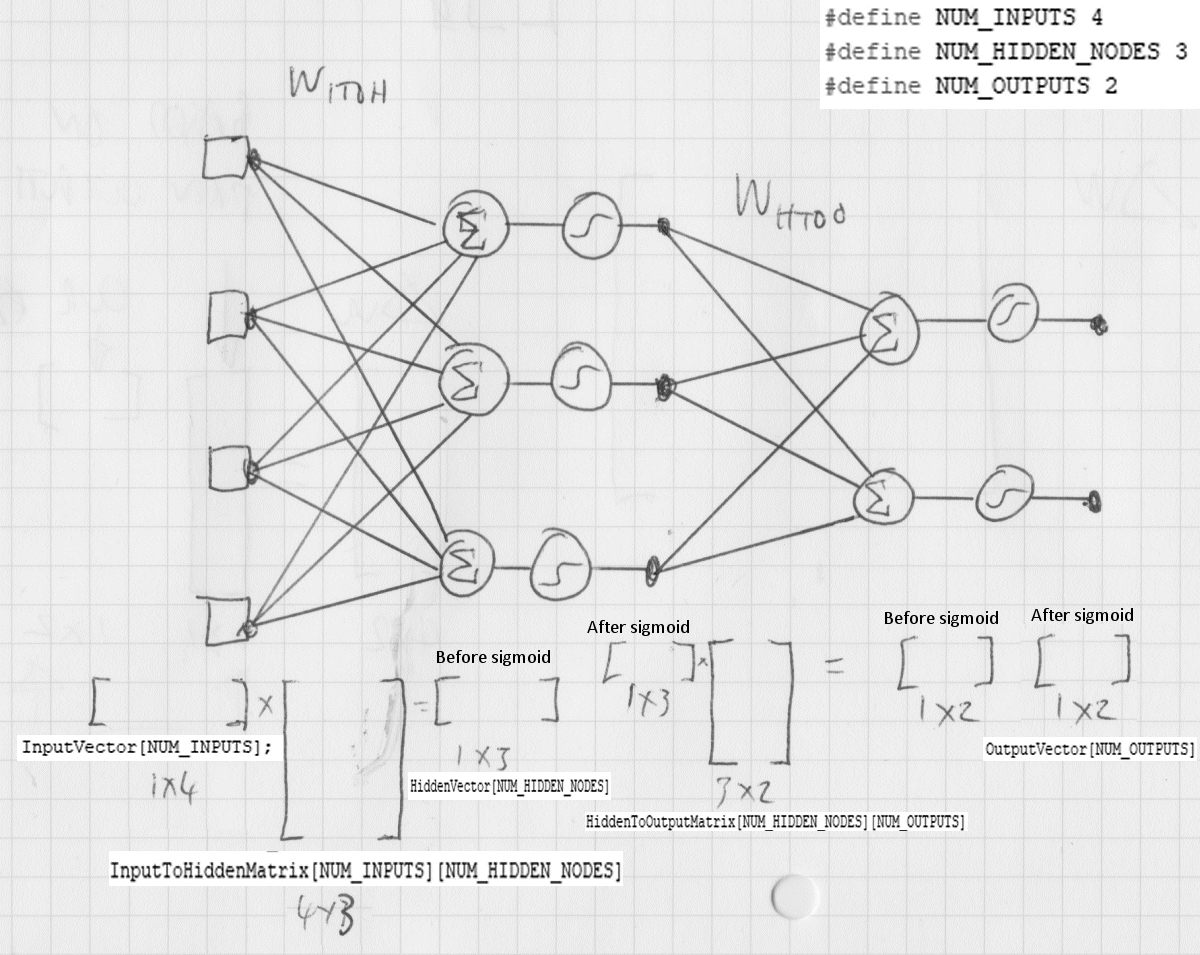
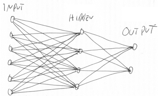
An even more practical example, imagine a question which is a vector of 6 numbers and an answer which is a vector of 2 numbers, what would the neural network look like?

The first thing you have to do is work out the size of all the three vectors and the two matrices.

Well I've heard it said, it has been hinted that, maybe suggested, that the size of the hidden nodes vector should be, could be, may be, between the number of input and outputs. So if we have 6 inputs and 2 outputs then 4 hidden nodes would be a good guess. Here's a drawing of the neural network:


Now the connections between the input and hidden and hidden and output are most easily represented as matrices...

So in our example we know the size of all the matrices and all the vectors. The number of rows is the number of inputs and the number of columns is the number of outputs of each block of connections.

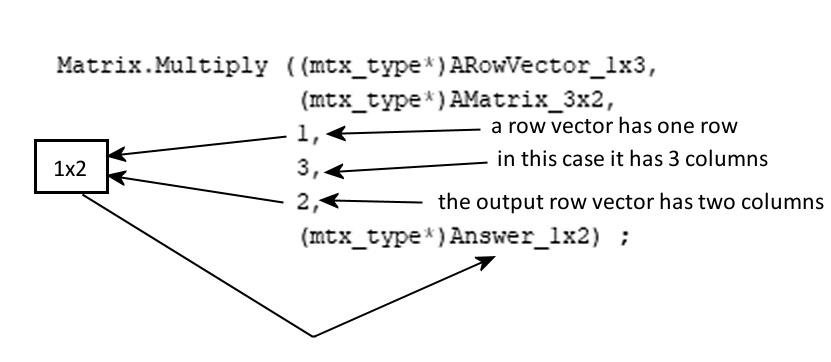
I used a mnemonic when I started studying matrix maths, RC = Roman Catholic = you have to follow the rules. The rules are:
  1. Always write the size as (number of Rows) x (number of Columns), RxC.
  2. When multiplying two matrices R1xC1 and R2xC2 then C1 and R2 must be equal.
  3. When multiplying two matrices R1xC1 and R2xC2 then the resulting matrix is of size R1xC2

This is all illustrated better graphically:


What all this means is that once we have decided on the number  of inputs, the number of outputs and the number of hidden nodes the sizes of the two intermediate matrices are also decided for us. In Arduino C we can simply use defines like this:

#define NUM_INPUTS 6
#define NUM_HIDDEN_NODES 4
#define NUM_OUTPUTS 2

And then use those constants to create the 2 matrices as well as the 3 vectors.

I've skipped one bit in the forward action of the neural network. That is the connection between the h'1... and h1 values. The h'1... values are calculated from the h1... values using the sigmoid function, as shown below:


As an aside the sigmoid function...

...is used because
  1. Whatever the input x is (from -infinity to +infinity) the output y is always between 0 and 1. This means that numbers in the network don't get extremely positively large or negatively large. As you can see above by the time x is +10, y practically is 1.0
  2. It has an easy to calculate derivative, which is used in training the network by back propagation
But that is an aside, see...
...for a more detailed explanation

The sigmoid is also used for o1' to o1 etc.

And here is the function which would query a neural network on the Arduino:


// Given the inputs and the weights in the matrices calculate the outputs
void QueryTheNeuralNetwork (mtx_type* InVector, mtx_type* OutVector)
{
    // Use inputs and first matrix to get hidden node values...
    Matrix.Multiply((mtx_type*)InVector,
                    (mtx_type*)gInputToHiddenMatrix,
                    1, // rows in InputVector (a vector, so 1)
                    NUM_INPUTS, // columns in InputVector
                    NUM_HIDDEN_NODES, // columns in InputToHiddenMatrix
                    (mtx_type*)gHiddenOutputs); // This is the output of Multiply

    // Now we have values in the gHiddenOutputs
    // i.e. we have the summed weights*inputs in the hidden nodes

    // Transform hidden node values using sigmoid...
    for (int hn = 0 ; hn < NUM_HIDDEN_NODES ; hn++) {
        double OldHiddenNodeValue = gHiddenOutputs[hn] ;
        double NewHiddenNodeValue =  Sigmoid (OldHiddenNodeValue) ;
        gHiddenOutputs[hn] = NewHiddenNodeValue ;
    }

    // Do (sigmoided hidden node values) x (second matrix) to get outputs
    Matrix.Multiply((mtx_type*)gHiddenOutputs,
                    (mtx_type*)gHiddenToOutputMatrix,
                    1, // rows in HiddenVector (a row vector, so 1)
                    NUM_HIDDEN_NODES, // columns in gHiddenOutputs
                    NUM_OUTPUTS, // columns in InputToHiddenMatrix
                    (mtx_type*)OutVector); // This is the output of this function

    // Transform output node values using sigmoid...
    for (int o = 0 ; o < NUM_OUTPUTS ; o++) {
        const double OldOutputValue = OutVector[o] ;
        const double NewOutputValue = Sigmoid (OldOutputValue) ;
        OutVector[o] = NewOutputValue ;
    }

    // "answer" is now inside OutputVector!
    // and the current hidden node values are in gHiddenNodes
}


Note that there are two matrices and three vectors, just as in the diagram at the beginning of this article.

The sigmoid function in Arduino code can be written like this:

 // Implement y = Sigmoid(x)
double Sigmoid (const double x)
{
    double y = 1.0/(1.0 + exp(-x)) ;
    return y ;
}

So far so good. But how do we adjust the weights (change the matrices) during training of the neural network?  How do we do the back propagation bit? And what on earth are hidden errors?

We'll get there, here's Part 2.


Neural Networks on the Arduino Part 7 : The complete source code.


// MatrixANNAndTrain, Created by Owen F. Ransen 28th March 2020

#include <MatrixMath.h>

// To decide the type of test one of these should be 1 and the other 0
#define XOR_TEST 0
#define POSITION_TEST 1

#if XOR_TEST+POSITION_TEST != 1
#error: set one or the other to 1 please.
#endif

#if XOR_TEST
#define NUM_INPUTS 2
#define NUM_HIDDEN_NODES 6
#define NUM_OUTPUTS 2
#define NUM_TRAINING_SAMPLES 35000


#elif POSITION_TEST
#define NUM_INPUTS 5
#define NUM_HIDDEN_NODES 4
#define NUM_OUTPUTS 2
#define
NUM_TRAINING_SAMPLES 8000
#endif

// These matrices must always exist, hence they are global
mtx_type gInputToHiddenMatrix[NUM_INPUTS][NUM_HIDDEN_NODES];
mtx_type gHiddenToOutputMatrix[NUM_HIDDEN_NODES][NUM_OUTPUTS];

// Useful to have this as a global so that after QueryTheNetwork we know what the
// hidden outputs were
mtx_type gHiddenOutputs[NUM_HIDDEN_NODES];

// This is the learning rate
const double Alpha = 0.1 ;

// Implement y = Sigmoid(x)
double Sigmoid (const double x)
{
    double y = 1.0/(1.0 + exp(-x)) ;
    return y ;
}


// Outer product, from two vectors form a matrix
// C = A*B
// A is a column vector (vertical and has lots of rows)
// B is a row vector (horizontal and has lots of columns)
// C must have space for mRows and nColumns for this to work.
void OuterProduct(mtx_type* A, mtx_type* B, int mRows, int nColumns, mtx_type* C)
{
    int ra, cb;
    for (ra = 0; ra < mRows; ra++) {
        for(cb = 0; cb < nColumns; cb++)
        {
            // C[ra][cb] = C[ra][cb] + (A[ra] * B[cb]);
            C[(nColumns * ra) + cb] = A[ra] * B[cb];
        }
    }
}


// Here we randomly initialise the weights in the neural network matrix
// This happens before training.
void RandomInitWeights (mtx_type* WeightsMatrix,
                        int iNumRows,
                        int iNumColumns)
{
    for (int row = 0; row < iNumRows; row++) {
        int iRowPart = (row*iNumColumns) ;
        for (int col = 0; col < iNumColumns; col++) {
            int iIdx = iRowPart + col ;
            // It has been suggested that a good starting point
            // is to have weights from -0.5 to +0.5
            WeightsMatrix[iIdx] =  (random (0,1001)/1000.0) - 0.5 ; 
        }
    }
}


// Given the inputs and the weights in the matrices calculate the outputs
void QueryTheNeuralNetwork (mtx_type* InVector, mtx_type* OutVector)
{
    // Use inputs and first matrix to get hidden node values...
    Matrix.Multiply((mtx_type*)InVector,
                    (mtx_type*)gInputToHiddenMatrix,
                    1, // rows in InputVector (a vector, so 1)
                    NUM_INPUTS, // columns in InputVector and rows in gInputToHiddenMatrix
                    NUM_HIDDEN_NODES, // columns in InputToHiddenMatrix
                    (mtx_type*)gHiddenOutputs); // This is the output of Multiply

    // Now we have values in the gHiddenOutputs
    // i.e. we have the summed weights*inputs in the hidden nodes

    // Transform hidden node values using sigmoid...
    // Go from h'1 to h1 in the diagram
    for (int hn = 0 ; hn < NUM_HIDDEN_NODES ; hn++) {
        double OldHiddenNodeValue = gHiddenOutputs[hn] ;
        double NewHiddenNodeValue =  Sigmoid (OldHiddenNodeValue) ;
        gHiddenOutputs[hn] = NewHiddenNodeValue ;
    }

    // Do (sigmoided hidden node values) x (second matrix) to get outputs
    Matrix.Multiply((mtx_type*)gHiddenOutputs,
                    (mtx_type*)gHiddenToOutputMatrix,
                    1, // rows in HiddenVector (a row vector, so 1)
                    NUM_HIDDEN_NODES, // columns in gHiddenOutputs and rows in gHiddenToOutputMatrix
                    NUM_OUTPUTS, // columns in InputToHiddenMatrix
                    (mtx_type*)OutVector); // This is the output of this function

    // Transform output node values using sigmoid...
    for (int o = 0 ; o < NUM_OUTPUTS ; o++) {
        const double OldOutputValue = OutVector[o] ;
        const double NewOutputValue = Sigmoid (OldOutputValue) ;
        OutVector[o] = NewOutputValue ;
    }

    // "answer" is now inside OutputVector!
    // and the current hidden node values are in gHiddenNodes
}


// Change the weights matrix so that it produces less errors
void UpdateWeights (int iNumInputNodes,  mtx_type* InputValues, // a column vector
                    int iNumOutputNodes, mtx_type* OutputValues, // a row vector
                    mtx_type* ErrorValues, // same size as output values
                    mtx_type* WeightMatrix) // This is an input and output
{
    // This is just to keep sizes of matrices in mind
    int iNumRows = iNumInputNodes ;
    int iNumCols = iNumOutputNodes ;
   
    // The f "horizontal" row vector is formed from
    // alfa*(error*(output*(1-output)) in each column
    // Initialised from errors and outputs of this layer, and so has the same
    // size as the error vector and output vector
    mtx_type f[iNumOutputNodes] ;

    for (int col = 0 ; col < iNumOutputNodes ; col++) {
        // The outouts have been created using the sigmoid function.
        // The derivative of the sigmnoid is used to modifiy weights.
        // Fortunately, because we have the outputs values, the derivative
        // is easy to calculate...Look up derivative of sigmod on the interweb
        const double SigmoidDerivative = OutputValues[col]*(1.0-OutputValues[col]) ;
        f[col] = Alpha*ErrorValues[col]*SigmoidDerivative ;
    }

    // The "vertical" column vector is the inputs to the current layer

    // Now we can do the outer product to form a matrix from a
    // a column vector multiplied by a row vector...
    // to get a matrix of delta weights
    mtx_type ErrorDeltasMatrix [iNumRows*iNumCols] ;
    OuterProduct((mtx_type*)InputValues, f, iNumRows, iNumCols, (mtx_type*)ErrorDeltasMatrix) ;

    // Now we have the deltas to add to the current matrix
    // We are simply doing OldWeight = OldWeight+DeltaWeight here
    for (int row = 0 ; row < iNumRows ; row++) {
        for (int col = 0 ; col < iNumCols ; col++) {
            int iIndex = (row*iNumCols)+col ;
            WeightMatrix[iIndex] = WeightMatrix[iIndex] + (ErrorDeltasMatrix[iIndex]) ;
        }
    }

}

// Given an input and a target find the error and change the weights to reduce the error
// We call UpdateWeights twice.
// You can find the equivalent in the python by searching for "def train"
void TrainOnOneSample (mtx_type* Ins,      // The input
                       mtx_type* Targets) // The ideal output
{
    // Ask what the answer would be with the current weights...
    mtx_type TestOutputs[NUM_OUTPUTS] ;
    QueryTheNeuralNetwork (Ins, TestOutputs) ; // Sets gHiddenOutputs too

    //# error is target - current_output
    // output_errors = targetscol - final_outputs
    mtx_type OutputErrors [NUM_OUTPUTS] ;
    for (int e = 0 ; e < NUM_OUTPUTS ; e++) {
        OutputErrors[e] =  Targets[e] - TestOutputs[e] ;
    }
     
    // Update the weights of the connections from output to hidden, gHiddenToOutputMatrix
    // The hidden outputs are the inputs into the final layer
    UpdateWeights (NUM_HIDDEN_NODES,gHiddenOutputs, // here are the inputs into final layer
                   NUM_OUTPUTS,TestOutputs, // outputs from final layer
                   (mtx_type*)OutputErrors, // final layer outputs errors, calculated above
                   (mtx_type*)gHiddenToOutputMatrix) ; // connections of final layer to be updated
     
    // update the weights for the links between the input and hidden layers
    // We need the hidden layer errors for that
    // Hidden layer error is the output errors split by weights recombined at hidden nodes
    // This is done by multiplying the transpose of the output matrix by the output errors
    // In Python: hidden_errors = numpy.dot(self.who.T, output_errors)
    mtx_type HiddenToOutputTranspose [NUM_OUTPUTS][NUM_HIDDEN_NODES] ; // notice reverse sizes
    Matrix.Transpose((mtx_type*)gHiddenToOutputMatrix,    // Original matrix
                     NUM_HIDDEN_NODES,         // Rows in original matrix
                     NUM_OUTPUTS,              // Cols in original matrix
                     (mtx_type*)HiddenToOutputTranspose)  ; // Transposed matrix

    // We've just made the transpose, now use it to calculate the hidden errors
    mtx_type HiddenErrors[NUM_HIDDEN_NODES] ;
    Matrix.Multiply ((mtx_type*)OutputErrors,
                     (mtx_type*)HiddenToOutputTranspose,
                     1, // rows in the input
                     NUM_OUTPUTS, // columns in the input, rows in the matrix
                     NUM_HIDDEN_NODES,
                     (mtx_type*)HiddenErrors) ; // Output 1 row and NUM_HIDDEN_NODES columns

    // The hidden outputs are the outputs of the hidden  layer
    UpdateWeights (NUM_INPUTS,Ins, // inputs into hidden layer
                   NUM_HIDDEN_NODES,gHiddenOutputs, // outputs from hidden layer
                   HiddenErrors, 
                   (mtx_type*)gInputToHiddenMatrix) ; // connections of first layer


#define QUERY_AS_YOU_UPDATE 1

#if QUERY_AS_YOU_UPDATE
    static int iDbgFlag = 0 ;

    if (iDbgFlag == 300) {
        mtx_type TestResultVector[NUM_OUTPUTS] ;
        QueryTheNeuralNetwork ((mtx_type*)Ins, (mtx_type*)TestResultVector) ;
   
        // Show the (hopefully miniscule) errors
        double Error = abs(Targets[0] - TestResultVector[0]) ;
        char sErr [10] ;
        dtostrf(Error, 6, 3, sErr ); // string will be 6 wide and 3 decimal point
       
        Serial.print ("Target = ") ; Serial.print (Targets[0]) ;
        Serial.print (", Output = ") ; Serial.print (TestResultVector[0]) ;
        Serial.print (", Error = ") ; Serial.println (sErr) ;          
        iDbgFlag=0 ;
    }
    iDbgFlag++;
   
#endif // QUERY_AS_YOU_UPDATE
}

void setup()
{
    Serial.begin(9600);

    // Setup the weights randomnly for later training...
    RandomInitWeights ((mtx_type*)gInputToHiddenMatrix,
                       NUM_INPUTS,
                       NUM_HIDDEN_NODES) ;
    RandomInitWeights ((mtx_type*)gHiddenToOutputMatrix,
                       NUM_HIDDEN_NODES,
                       NUM_OUTPUTS) ;
}

#if POSITION_TEST
// This creates a test input vector and the ideal output for that input
void CreatePositionTrainingSample (mtx_type* TrainInputVector, mtx_type* TrainTargetVector)
{
    // A check to stop silly errors as you meddle with the code...
    if (NUM_OUTPUTS != 2) {
        Serial.print ("Training sample error, I want 2 outputs!") ;
    }
 
    // Choose a place from 0 to NUM_INPUTS..
    int iPos = random (0,NUM_INPUTS) ;  
   
    // Make a vector with a spike at the randomly chosen iPos
    for (int i = 0 ; i < NUM_INPUTS ; i++) {
        if (i == iPos) {
            TrainInputVector[i] = 1.0 ;      
        } else {
            TrainInputVector[i] = 0.0 ;
        }
    }
    // Now we have an input vector with a single non zero value

    // What is the expected output number?
    // We want one output to be at the "value of the position" so to speak
    double OutputValue1 = (double)iPos/double(NUM_INPUTS-1) ;

    // Just to have more than one output...
    // ...make other output to be at the "opposite of the value of the position"
    double OutputValue2 = 1.0 - OutputValue1 ;

    // This is the idea correct answer...
    TrainTargetVector[0] = OutputValue1 ;
    TrainTargetVector[1] = OutputValue2 ;
}
#endif // POSITION_TEST


#if XOR_TEST

// Create function which will give training samples from this logic table:
// inputs       XOR    XNOR
// 0    0        0      1
// 0    1        1      0
// 1    0        1      0
// 1    1        0      1

void CreateXORTrainingSample (mtx_type* TrainInputVector, mtx_type* TrainTargetVector)
{
    // A check to stop silly errors as you meddle with the code...
    if (NUM_OUTPUTS != 2) {
        Serial.print ("Training sample error, I want 2 outputs!") ;
    }
    if (NUM_INPUTS != 2) {
        Serial.print ("Training sample error, I want 2 inputs!") ;
    }
    
    // Choose a row in the truth table...
    int iWhichRow = random (0,4) ;  // will give me a number from 0 to 3 inclusive

    if (iWhichRow == 0) {
        TrainInputVector[0] = 0 ;     
        TrainInputVector[1] = 0 ;  
        TrainTargetVector[0] = 0 ;  
        TrainTargetVector[1] = 1 ;  
       
    } else if (iWhichRow == 1) {
        TrainInputVector[0] = 1 ;     
        TrainInputVector[1] = 0 ;     
        TrainTargetVector[0] = 1 ;  
        TrainTargetVector[1] = 0 ;  

    } else if (iWhichRow == 2) {
        TrainInputVector[0] = 0 ;     
        TrainInputVector[1] = 1 ;     
        TrainTargetVector[0] = 1 ;  
        TrainTargetVector[1] = 0 ;  
   
    } else {
        TrainInputVector[0] = 1 ;     
        TrainInputVector[1] = 1 ;     
        TrainTargetVector[0] = 0 ;  
        TrainTargetVector[1] = 1 ;  
    }
}

#endif // XOR_TEST

// Train the neural network on many test cases
void RunMultipleTrain ()
{
    for (long t = 0 ; t <
NUM_TRAINING_SAMPLES; t++) {
        // Create a perfect test case, input and required output...
        mtx_type TrainInputVector[NUM_INPUTS] ;
        mtx_type TrainTargetVector[NUM_OUTPUTS] ;

#if XOR_TEST      
        CreateXORTrainingSample (TrainInputVector,TrainTargetVector) ;
#elif POSITION_TEST
        CreatePositionTrainingSample (TrainInputVector,TrainTargetVector) ;
#endif

        // This will modify the NN weights to get the outputs closer to the target
        TrainOnOneSample (TrainInputVector,TrainTargetVector) ;      
    }
}


void loop()
{
    // Train the neural network...
    RunMultipleTrain () ;
  
    // Test the trained neural network...
    const int ikNumTests = 10 ;

    for (int t = 0 ; t < ikNumTests ; t++) {
        Serial.println ("") ;
        // Create a perfect test case, input and required output...
        mtx_type TestInputVector[NUM_INPUTS] ;
        mtx_type TestTargetVector[NUM_OUTPUTS] ;

#if XOR_TEST      
        CreateXORTrainingSample (TestInputVector,TestTargetVector) ;
#else
        CreatePositionTrainingSample (TestInputVector,TestTargetVector) ;
#endif
       
        // Ask the NN what it thinks the outputs are...
        mtx_type TestResultVector[NUM_OUTPUTS] ;
        QueryTheNeuralNetwork ((mtx_type*)TestInputVector, (mtx_type*)TestResultVector) ;

        // Show the (hopefully miniscule) errors
        for (int op = 0 ; op < NUM_OUTPUTS ; op++) {
            double Error = TestTargetVector[op] - TestResultVector[op] ;
            Serial.print ("Target = ") ; Serial.print (TestTargetVector[op]) ;
            Serial.print (", Output = ") ; Serial.print (TestResultVector[op]) ;
            Serial.print (", Error = ") ; Serial.println (Error) ;          
        }
    }

    while(1);
}